|
Introduction to Type-Tested
and Partially Type-Tested Assemblies
IEC 60439-1-1999-09, EN60349-1 and BS
EN60439-1 is Part 1 of the 439-series of standards and is the
main part covering the general requirements for type-tested and
partially type-tested assemblies. Parts 2, 3, and 4 of the standards
deal with the particular requirements for certain specialised
forms of assemblies (see below).
Low-voltage switchgear and controlgear assemblies
- -439-1: Specification
for type-tested and partially type-tested assemblies.
- -439-2: Particular requirements
for busbar trunking systems.
- -349-3: Particular requirements
for assemblies intended to to be installed where unskilled persons
have access to their use.
- -439-4: Particular requirements for assemblies
for construction sites.
The need to conform to standards.
Low-voltage switchgear and controlgear come
under the EU Low Voltage Directive, and since January 1st 1997,
all new assemblies intended for use within the EU member states
must be CE - marked to indicate that they conform with the essential
safety requirements of this Directive.
The Directive requires electrical equipment
to be safe and constructed in accordance with the principles generally
accepted within the member states of the EU as constituting good
engineering practice in relation to safety matters. It requires
that the electrical equipment (assembly), together with its components,
is made in a way that ensures it can be safely and properly assembled
and connected.
It also requires that measures are taken to
ensure that protection is assured against various hazards which
might arise from the electrical equipment or by external influences
on it.
Some of the hazards listed by the Directive
include:
- Direct and indirect contact with live parts
- Dangerous temperatures, arcs or radiation
- Overloading
- Insulation failures
- Mechanical failures
- Expected environmental conditions
- Non-electrical dangers caused by the assembly
There is, of course, the proviso that an assembly
is used in an application for which it was made, and that it is
properly installed.
TYPE-TESTED ASSEMBLY (TTA) IEC 60439-1-1999-09
CLAUSE 2.1.1.1
A low-voltage switchgear and controlgear assembly
conforming to an established type or system without deviations
likely to significantly influence the performance, from the typical
assembly verified to be in accordance with this standard.
Notes:
For various reasons, for example transport or production, certain
steps of assembly may take place outside the factory of the manufacturer
of the TTA. Such an assembly is considered as a TTA provided the
assembly is performed in accordance with the manufacturers instructions
in such a manner that compliance of the established type or system
with this standard is assured, including submission to applicable
routine test.
PARTIALLY TYPE-TESTED LOW-VOLTAGE SWITCHGEAR
AND CONTROLGEAR ASSEMBLY (PTTA) IEC 60439-1-1999-09 CLAUSE 2.1.1.2
A low-voltage switchgear or controlgear assembly,
containing both type-tested and non-type-tested arrangements provided
that the latter are derived (e.g. by calculation) from type tested
arrangements which have complied with the relevant tests. (see
table section 4.5.4)
Internal Form of Separation
IEC 439-1, Amendment 2 1996-11 gives the
following guidelines for the different separation types.
One or more of the following conditions can
be obtained by dividing ASSEMBLIES by means of partitions or barriers
(metallic or non-metallic) into separate compartments or enclosed
protected spaces:
- Protection against contact
with hazardous parts belonging to the adjacent functional units.
The degree of protection shall be at least IPXXB.
- Protection against the passage of solid
foreign bodies from one unit of an ASSEMBLY to an adjacent unit.
The degree of protection shall be at least IP2X.
Unless otherwise stated by the manufacturer,
both conditions shall apply.
NOTE: The degree of protection IP2X covers the degree of protection
IPXXB
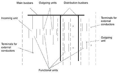
The following are typical forms of separation
by partitions:
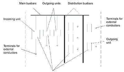
FORM 1 No separation.

FORM 2A Separation of busbars from the functional
units. The terminals for external conductors do not need to be
separated from the busbars.

Degrees of protection
The system has been tested according to the
guidelines as described in IEC 60529 and passed the test conditions
for the IP 54 protection as laid down in Sub-clause 7.5 (first
characteristic numeral) and Sub-clause 8.4 (second characteristic
numeral).
The following is an extract from the Standard.
DEGREE OF PROTECTION
First characteristic
numeral |
Short description |
Second characteristic numeral |
Short description |
| 0 |
Non-protected |
0 |
Non-protected |
| 1 |
Protected against solid objects greater
than 50 mm |
1 |
Protected against dripping water |
| 2 |
Protected against solid objects greater
than 12 mm |
2 |
Protected against dripping water when
than 12 mm tilted up to 15° |
| 3 |
Protected against solid objects greater
than 2.5 mm |
3 |
Protected against spraying water |
| 4 |
Protected against solid objects greater
than 1 mm |
4 |
Protected against splashing water |
| 5 |
Dust-protected |
5 |
Protected against water jets |
| 6 |
Dust-tight |
6 |
Protected against heavy sea |
Rated Currents and Short-Circuit Currents of
3-phase Transformers
| No. of Transformers & Rated Output |
Rated Current Transformer |
Total Available Current |
Max. Prospective Short-Circuit Current |
| [kVA] |
[A] |
[A] |
[kA] |
|
1 x 500
2 x 500
|
722
722 |
722
1444 |
18.0
36.0 |
1 x 630
2 x 630
3 x 630 |
910
910
910 |
910
1820
2730 |
22,7
45.4
68.1 |
1 x 800
2 x 800
3 x 800 |
1156
1156
1156 |
1156
2312
3468 |
23,1
46.2
69.3 |
1 x 1000
2 x 1000
3 x 1000 |
1444
1444
1444 |
1444
2888
4332 |
28,9
57.8
86.7 |
1 x 1250
2 x 1250
3 x 1250 |
1805
1805
1805 |
1805
3610
5415 |
36,1
72.2
108.3 |
1 x 1600
2 x 1600
3 x 1600 |
2312
2312
2312 |
2312
4624
6936 |
37.0
74.0
111.0 |
1 x 2000
2 x 2000 |
2890
2890 |
2890
5780 |
46,2
92.4 |
| 1 x 2500 |
3610 |
3610 |
57,7 |
| 1 x 3150 |
4550 |
4550 |
72,7 |
The current ratings above are based on a voltage
of 450V. The short-circuit currents shown in this table are higher
than actual as they assure infinite power on the supply side and
do not take into account impedance of cables, busbars and connections
to breakers.
|


